
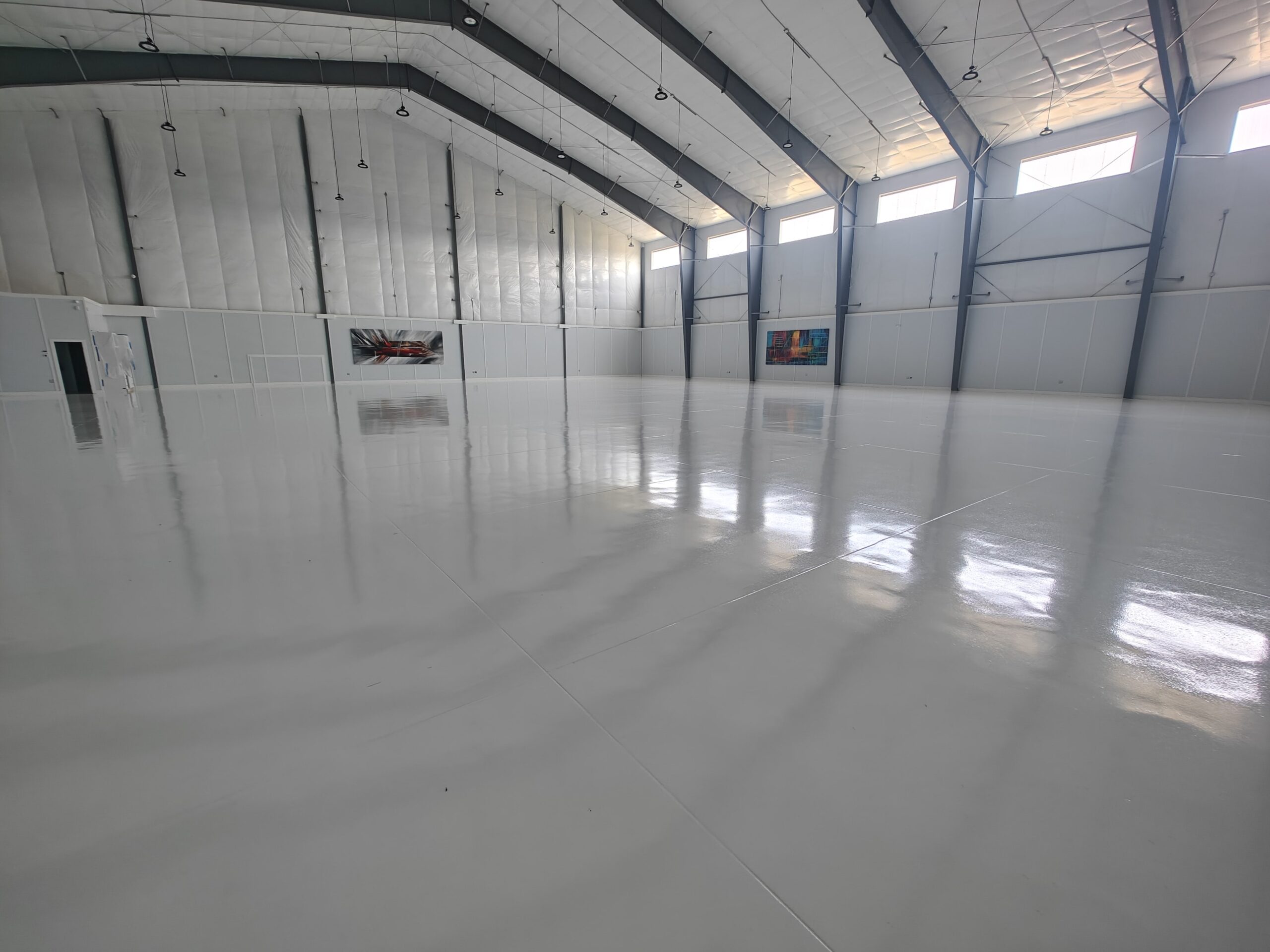
ESD & static control flooring
Electronics assembly, cleanroom and test environments where a discharge is a scrapped board or a failed audit. These floors are specified to a resistance range, installed over a grounding grid, and tested on completion — the number is the deliverable.
An ESD floor is a measurement, not a product.
A floor is static-dissipative because it tests within a resistance range, tied to a grounding grid that is actually connected. Plenty of floors are sold as ESD and never tested after installation, which means nobody knows whether the specification was met — until an audit asks, or a board fails and nobody can say why. We install to a target range, bond the grid properly, and hand over the test results as part of the documentation.
Where we are the right call
- Electronics assembly, rework and test areas
- Cleanroom and controlled-environment floors requiring static control
- Facilities working to an ANSI/ESD S20.20 programme
- Server, comms and battery rooms
- Existing ESD floors that no longer test within range
Where we will tell you something else
- Areas where ordinary anti-static properties are genuinely enough
- Buildings with no grounding provision and no plan to install one
- Spaces where ESD matting would serve at a fraction of the cost
- Any specification we cannot test and document on completion
What gets installed, and what it is rated for.
| Typical system | Static-dissipative epoxy over a copper grounding grid, bonded to the facility earth |
|---|---|
| Build thickness | 20–60 mils depending on whether a dissipative topcoat or a full conductive build is specified |
| Resistance range | Specified to the range your programme requires — commonly 1×10⁶–1×10⁹ Ω for static-dissipative |
| Standards | Installed to support an ANSI/ESD S20.20 programme; tested to ANSI/ESD S7.1 on completion |
| Grounding | Copper grid laid within the system at the specified spacing and bonded to the building earth at documented points |
| Verification | Point-to-point and point-to-ground resistance tested and recorded across the area, issued with the handover documentation |
| Surface preparation | Diamond grinding to CSP 2–3; slab moisture tested, since moisture changes the measured result |
| Return to service | Foot traffic 10–14 hrs · testing and full use 48–72 hrs |
| Warranty | Written workmanship warranty, terms by system |
How we keep you running while we work.
Every commercial proposal we issue includes a phasing plan and the hours each zone is out of service. If we cannot make the window work, we will tell you at the walk-through rather than halfway through the install.
Confirm the target
We agree the resistance range and the standard your programme works to before anything is specified.
The number firstGrid and prepare
Slab prepared and tested for moisture, then the grounding grid laid and bonded to documented points.
Grid documentedInstall off-shift
System laid around your assembly hours, area by area.
Around productionTest and document
Point-to-point and point-to-ground resistance tested across the area and issued with the handover pack.
Results in writingWhat facility managers ask us first.
How do we know it actually meets the spec?
Our existing ESD floor is failing its tests.
Do we need conductive or dissipative?
Walk the building with us.
An hour on site gets you a moisture reading, an honest assessment of the slab and the joints, a system recommendation, and a phasing plan that fits your operation. No obligation, and no pressure to decide on the spot.